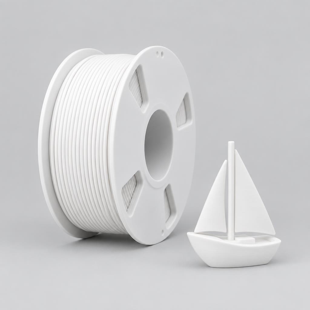
Standard
PLA
Easy to print, biodegradable, great for prototypes and decorative parts.
Technology
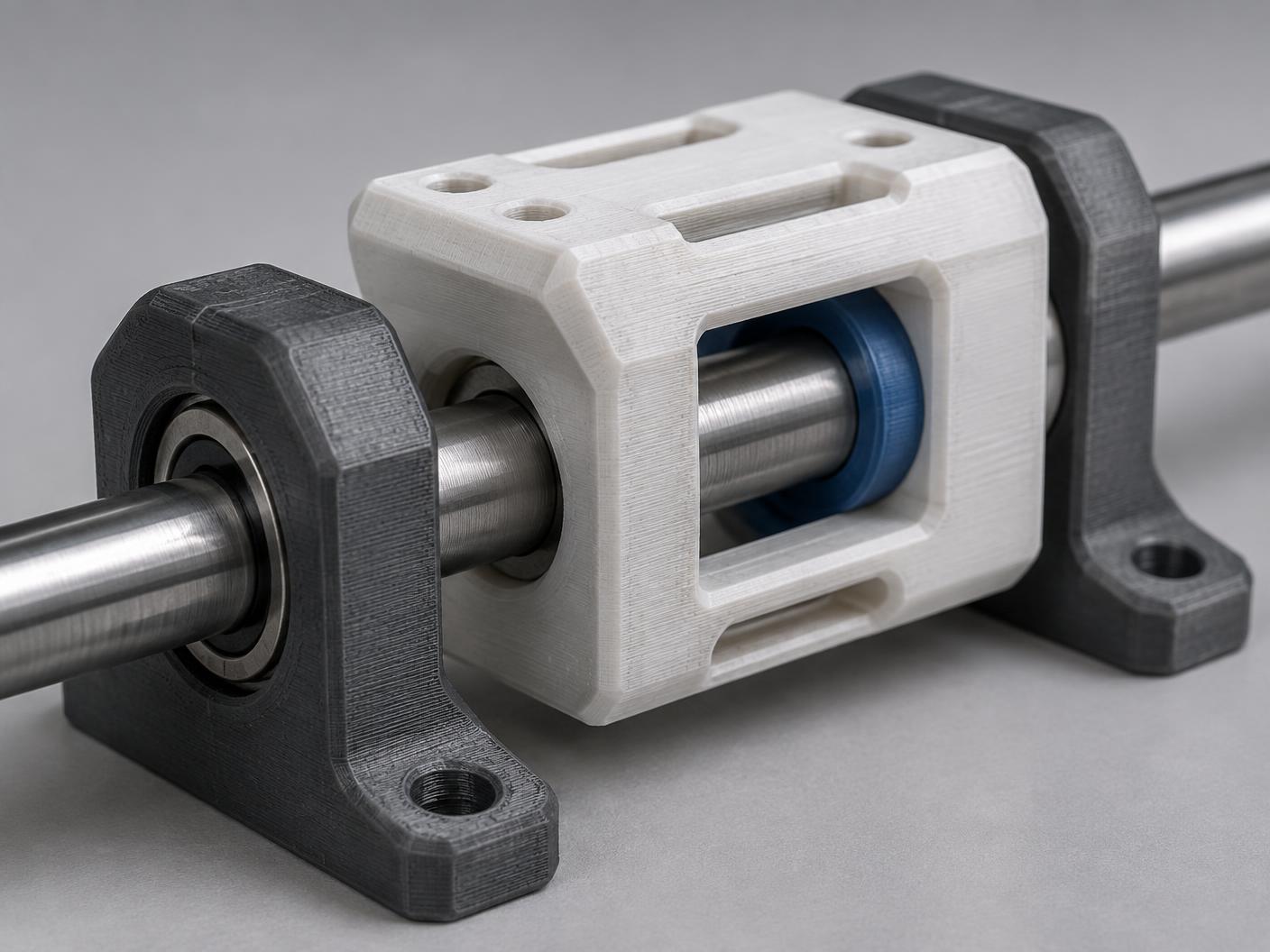
Functional parts, prototypes and fixtures printed in thermoplastics on a calibrated enclosed machine in Luxembourg.
Another CAD format? Request a manual quote
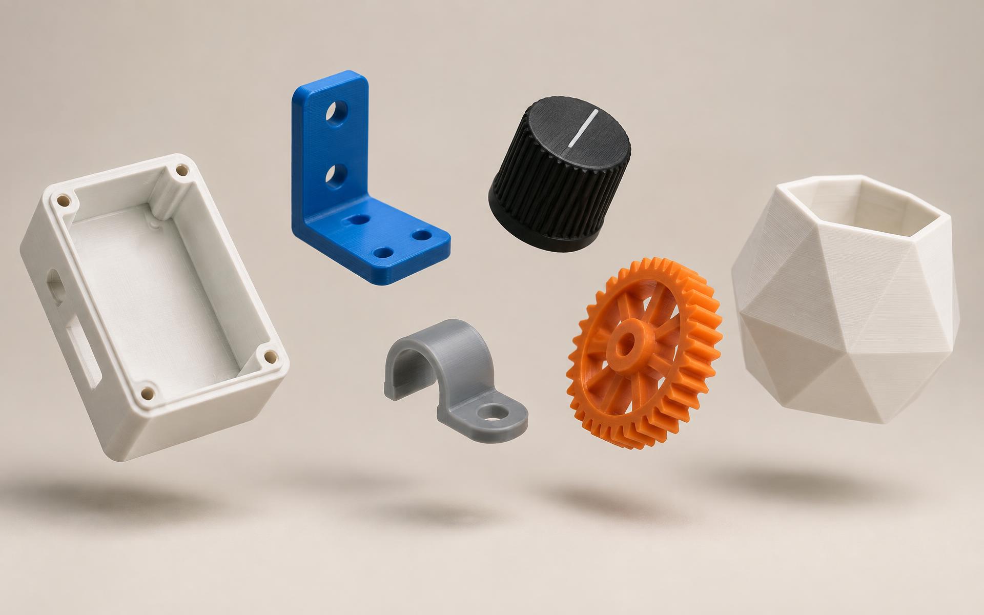
Made to your spec
Your material, colour, infill and finish — every part prints exactly how you configured it.
Production capability
We hold this tolerance on every part, whichever slicer settings we use. Layer height, infill and nozzle are production decisions we make for you.
From file to finished part
01 / Upload and check
The configurator checks the model against the machine envelope, lets you choose a stocked material and calculates the quote before you order.
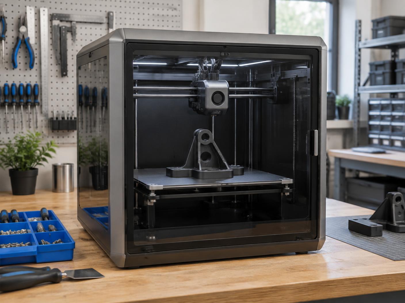
02 / Calibrated production
We choose orientation, layer height, infill and support strategy for the geometry and intended use. Layer direction matters because FDM parts are strongest in the plane of the build plate.
03 / Functional result
Controlled layer lines, clean edges and suitable clearances make FDM a practical choice for enclosures, brackets, fixtures and fitted assemblies.
A focused view of the live catalogue. Images, availability and starting prices update with the material catalogue.
Standard
Easy to print, biodegradable, great for prototypes and decorative parts.
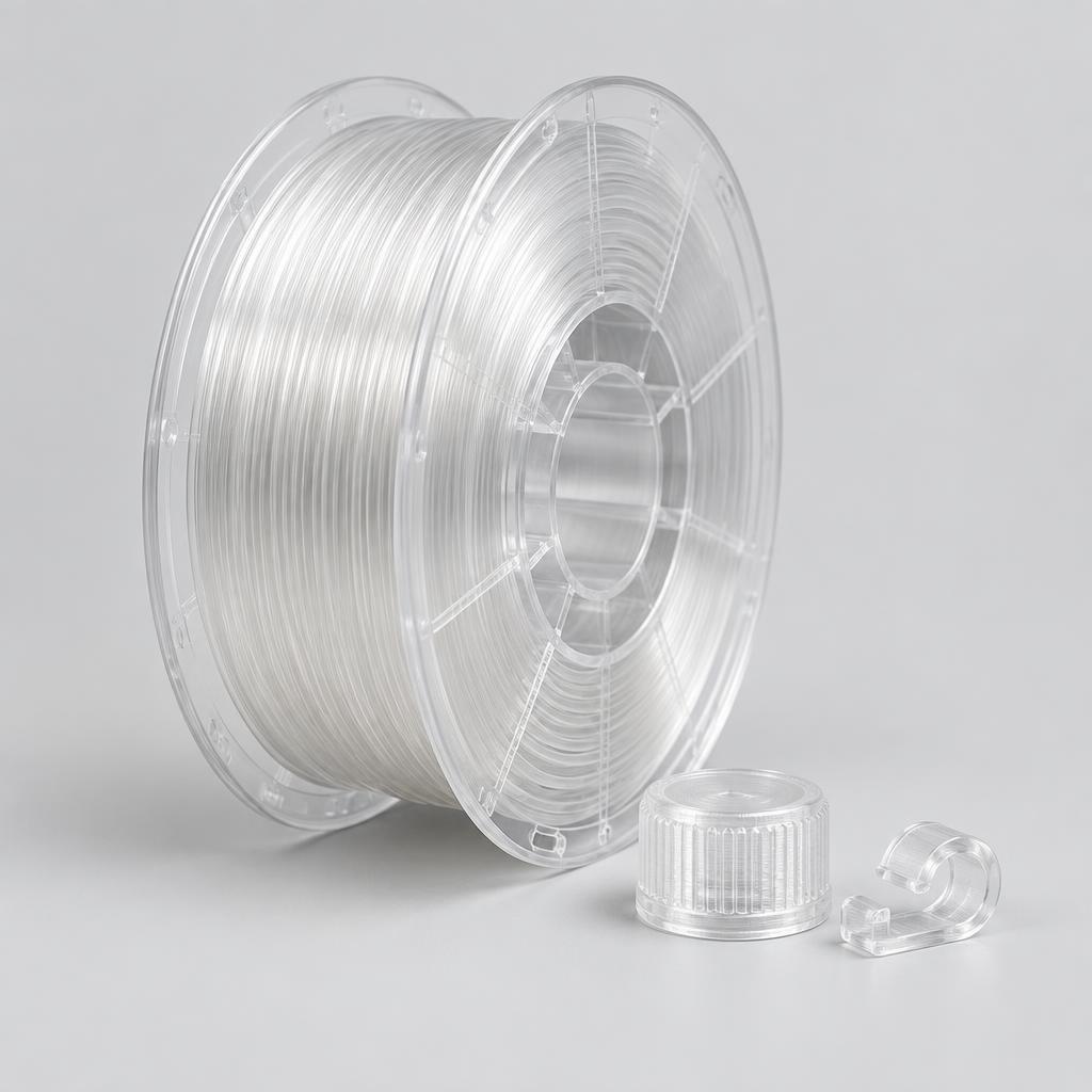
Standard
Tougher and more heat-resistant than PLA, good for functional parts.
Design rules
Use these practical limits before uploading. Open a rule for the complete recommendation.
Choose a material, fit type and nominal size to calculate a practical starting clearance.
Tolerance calculator
Per-side clearance
0.25 mm
Diametral clearance
0.50 mm
hole − shaft
Model the hole at
10.50 mm
for a 10.0 mm shaft
Base recommendation 0.25 mm. Tune in 0.05 mm steps from a small test print.
ABS and TPU are not in our current stock — we quote them as a special run by email. Email us for a quote.
Assumes a 0.4 mm nozzle at 0.2 mm layer height on a well-calibrated printer. For diameters under 3 mm, add another 0.05–0.10 mm per side to account for extrusion overlap on the inside of the hole.
| Material | Press fit | Sliding fit | Threads | Hinges |
|---|---|---|---|---|
| PLA | 0.10–0.15 mm | 0.20–0.30 mm | 0.20 mm | 0.30 mm |
| PETG | 0.15–0.20 mm | 0.25–0.35 mm | 0.25 mm | 0.35 mm |
Values are per-side clearance between mating surfaces. Double them when specifying diameter-on-diameter (hole vs. shaft).
These numbers assume a 0.4 mm nozzle at 0.2 mm layers on a calibrated machine. If a first assembly is too tight, adjust in 0.05 mm steps — the smallest change FDM reliably resolves. Print a small tolerance test alongside the real part rather than reprinting the whole assembly.
OBJ, 3MF, STEP or Rhino (3DM) file? Email it to us — our CAD engineer will review it and send a quote within 24 hours.